1. Product Components
Vehicle regulation 4-channel version |
NO | kit | Component details | Quantity | Legend |
1 | Main unit kit | Host | 1 unit |  |
Host harness | 1 piece |  |
Host fixing screws | 1 pack |  |
2 | Camera kit | Camera | 4 units |  |
Camera housing | 4 units |
Camera screws | 4 packs |  |
3 | Extension cable | Front camera extension cable | 1 piece |  |
Rear camera extension cable | 1 piece |
Left camera extension cable | 1 piece |
Right camera extension cable | 1 piece |
Display screen extension cable | 1 piece |
4 | Display screen | Display screen | 1 unit |  |
Display screen bracket | 1 unit |
Display screen fixing screws | 1 pack |  |
5 | Debugging tool | Remote control (requires 2 AA batteries, not included) | 1 unit |  |
Infrared extension cable | 1 piece |  |
Automatic calibration cloth | 1 set£¨4 pieces£© |  |
2. Installation tools
NO | Installation tools | Usage | Legend |
1 | ladder | drilling holes in the exterior of the vehicle |
|
2 | cordless drill |
|
3 | hole saw (size 18) |
|
4 | Phillips screwdriver | securing cameras/main unit |
|
5 | glass adhesive gun | drilling holes in the vehicle body waterproof treatment |
|
6 | black glass adhesive |
|
7 | zip ties | securing extension cable ducts |
|
8 | black adhesive tape | insulating wire harnesses |
|
9 | spare cables | extending ACC or signal lines |
|
10 | two 20-meter tape measures | workstation layout for calibration |
|
11 | two 5-meter tape measures |
|
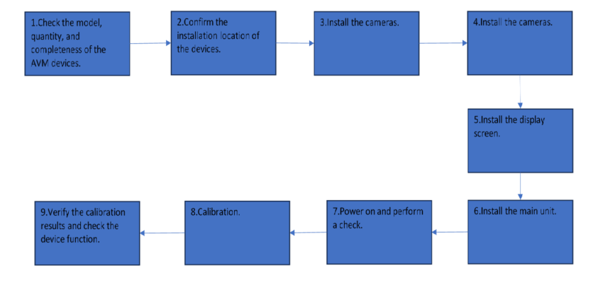
3. Installation Steps
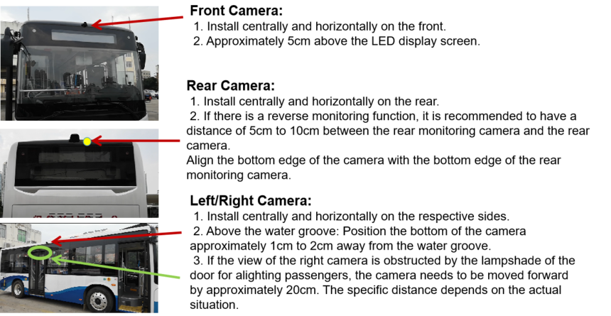
3.1.1 Camera Installation Position
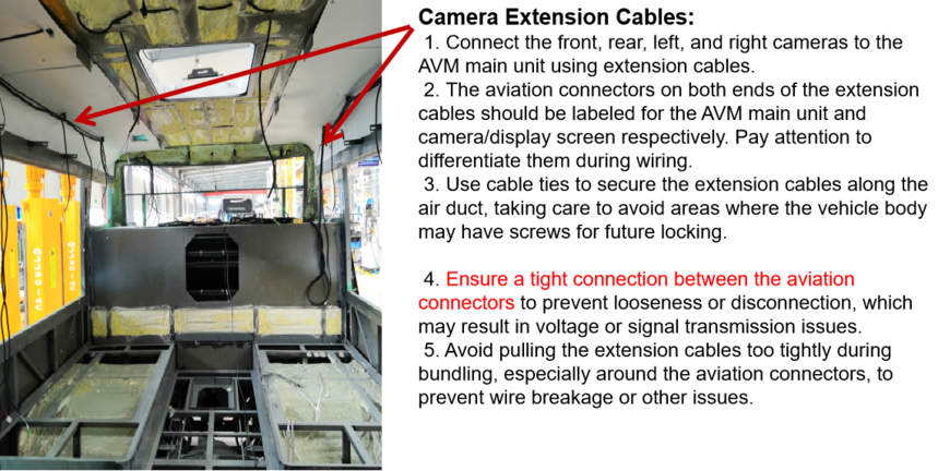
3.1.2 Extension Cable Installation Position
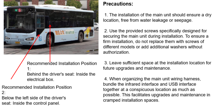
3.1.3 Main Unit Installation Position
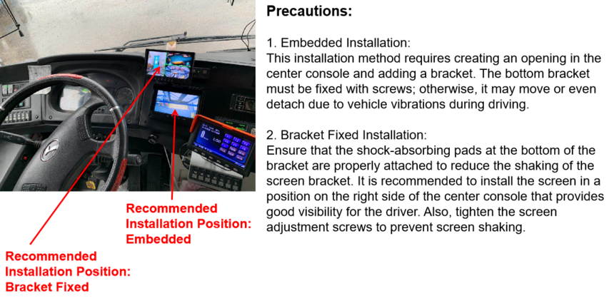
3.1.4 Display Screen Installation Position
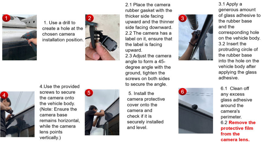
3.2 Camera Installation
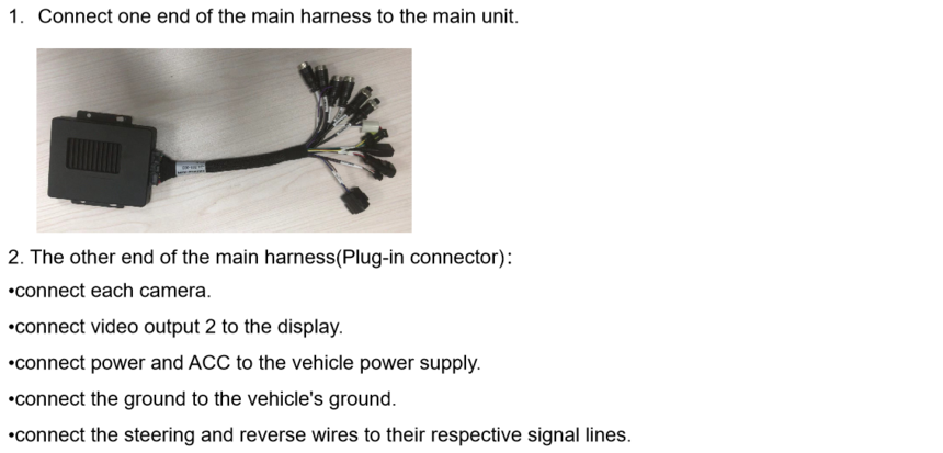
3.3 Main Unit Installation
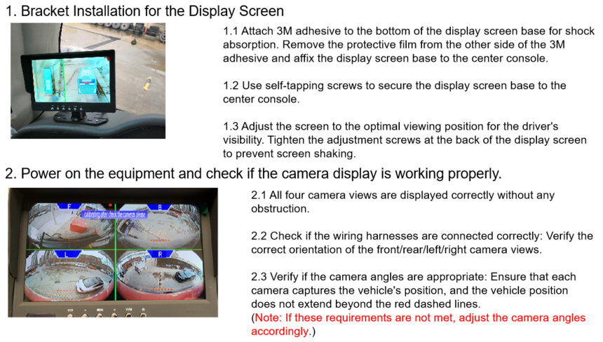
3.4 Display Screen Installation
